
Bus Tracker
Things used in this project
Hardware components

|
SORACOM Air Global IoT SIM | × 1 |
| Huawei 3G USB dongle (MS2131i) | × 1 | |
| Jun-Electron for Raspberry Pi 3 B+ 3.5 inch Touch Screen with Case | × 1 | |

|
Raspberry Pi 3 Model B | × 1 |

|
Raspberry Pi Zero Wireless | × 1 |
| 640x384, 7.5inch E-Ink display HAT | × 1 | |

|
Micro-USB to USB Cable (Generic) | × 1 |
Software apps and online services

|
AWS IoT | × 1 |

|
AWS DynamoDB | × 1 |

|
SORACOM Air IoT Connectivity Platform | × 1 |
Story
1.0 Introduction
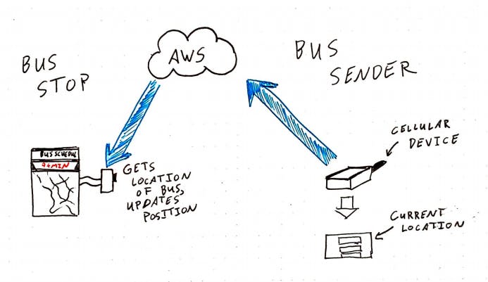
Tracking buses is something that a lot of larger cities have but smaller cities and towns don't. There are many that still rely on a printed schedule that isn't accurate and could be consistently wrong. I wanted to create a scalable solution that would be low cost. There would be one device on the bus that the bus driver would use to update their current location and then there would be a device at the bus stop that would update a display with how far the bus is away.
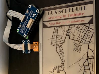
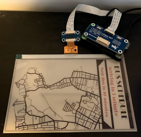
1.1 Bus Stop Device
The bus stop device needs to do two things - receive the updated location and update the e-ink display with that new location. I wanted to use an e-ink display because I wanted the bus stop device to require as little power as possible. E-ink displays only consume power when the display changes. Because my system only updates on a change, overnight and other periods of time when there are no buses, the display will show that there is currently no bus running. I used a raspberry pi zero W and a waveshare e-ink 7" display. I selected a three color display - red, white and black.
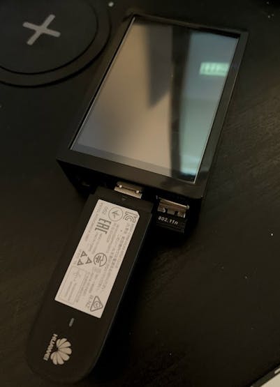
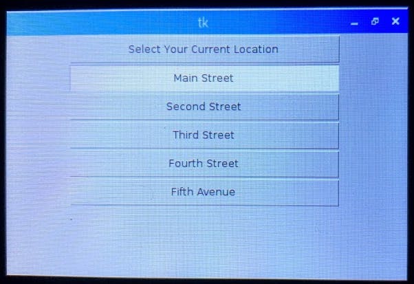
1.2 Bus Tracker Device
The bus tracker device also needs to do two things - take in the current location and send that information to a database. I used a raspberry pi 3 with a 3.5" touchscreen display along with the Huawei 3G Cellular device and the Soracom sim card. I made a simple interactive display using the Tkinter library in python.
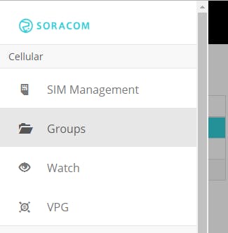
2.0 Setting up Soracom
First you should go through most of the tutorial of the soracom IoT starter kit. Those instructions have the user use AWS Harvest to send data to AWS and then get a text of that information. For this project, I wanted the information to update an AWS DynamoDB record with the most recent information. Please read these docs for additional information. Soracom also has a document about using AWS Harvest.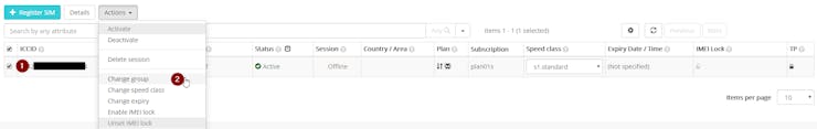
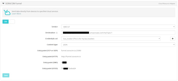
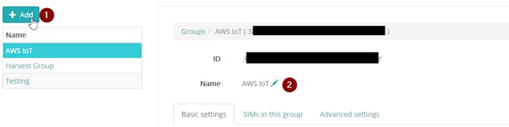
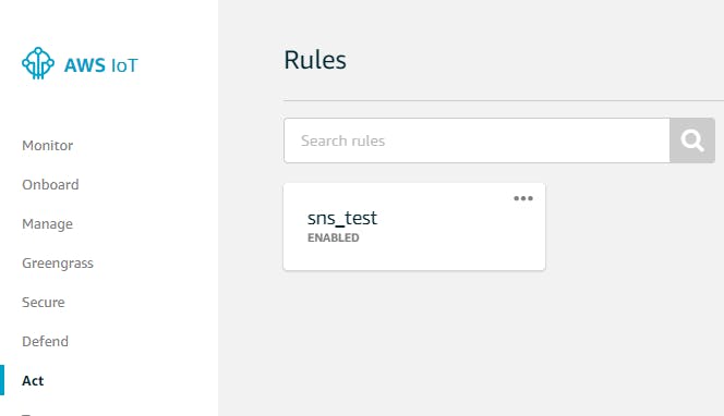
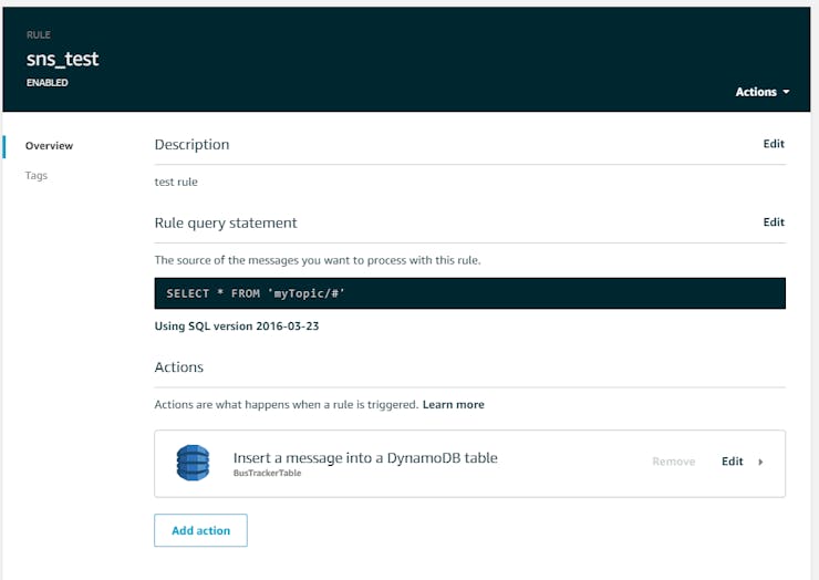
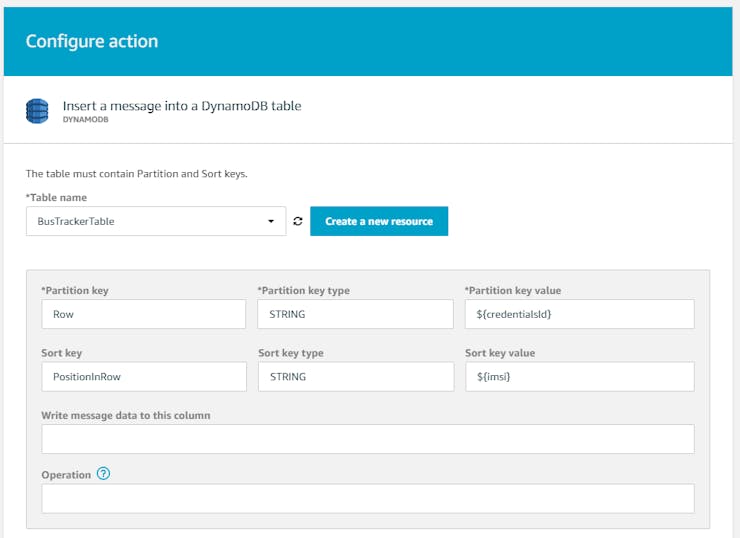
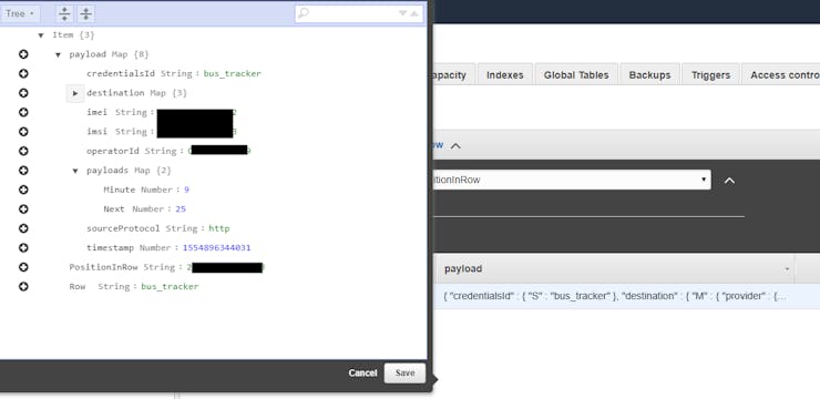
2.1 Setting up AWS Harvest
If you follow the Soracom guide on AWS Harvest using this link, you should be able to send a command from the raspberry pi and receive an email. We are going to edit that default so instead of receiving an email, we update a record in a AWS DynamoDB database. Create a database, I called mine BusTrackerTable to make it easy.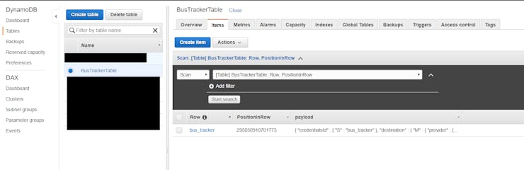
3.0 Putting it all together
Using the code in the description as well as the GitHub link below, assembly should be pretty simple. The Waveshare resources explain how to use the display and how to update it. The GitHub has the images that I used in my project for the e-ink display.
Here is the video demonstration of the system working.
4.0 Conclusion
For this project, I went with the assumption that the bus stop had WiFi. If it does not have WiFi, it would be fairly simple to add a cellular modem to the device. I didn't do this on my system because I only had one cellular device.
I also went with the assumption that the bus driver would be able to select the current location. I was debating whether or not having the bus device update the GPS position of the bus and then having the bus stop device interpret that GPS position and then calculate the distance away and estimate how much time it would take. The problem with that system is that I would have to send the position every 30 seconds or so which would waste time if the current bus was out of service. I also figured that one of the features that every bus does is notify bus riders of where it currently is. If I had a bus to use, I would just integrate that directly with the raspberry pi and have the location sent automatically.
Overall, I'm very happy about how this project turned out. I think that there I would require only very minor modifications in order to scale to multiple buses and multiple bus stops.